Types and Features of BOP Rams
Introduction
The blowout preventer ram is the result of more than 80 years of development of the blowout preventer group system. The first blowout preventer rams were developed in the early 1900s. A ram blowout preventer can only be sealed under the specific conditions for which the ram was designed.
The rams are interchangeable between ram blowout preventers of the same design and pressure rating. Casing rams are often used in place of pipe rams prior to casing or lining operations. Most rams can be locked in the closed position, operated manually and hydraulically, and support the weight of the entire drill column. Pipe rams cannot be installed upside down because they are designed to hold pressure in only one direction.

BOP Ram Assembly
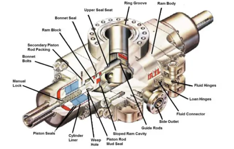
The main components of a ram blowout preventer include:
The ram body contains all the parts that allow the ram blowout preventer to operate.
Fluid connection is the hydraulic fluid connection port that operates the piston.
Side outlet, which is a connecting piece built into the ram body, allows fluid to circulate into or out of the wellbore.
The piston rod mud seal is a secondary seal that prevents the type of drilling fluid (OBM – WBM) from contaminating the internal seal on the piston rod.
The valve cover fixed by the valve cover bolt allows access to the ram body for replacement.
The emergency piston rod packing is a grease injection inlet that can be sealed on the piston rod when the main seal begins to leak.
Valve cover seal is an elastic seal that prevents wellbore fluid leakage under pressure.
The sealing seat is a replaceable component that can prevent the wear of the ram body by operating the ram plate. It can be replaced on-site.
BOP ram type
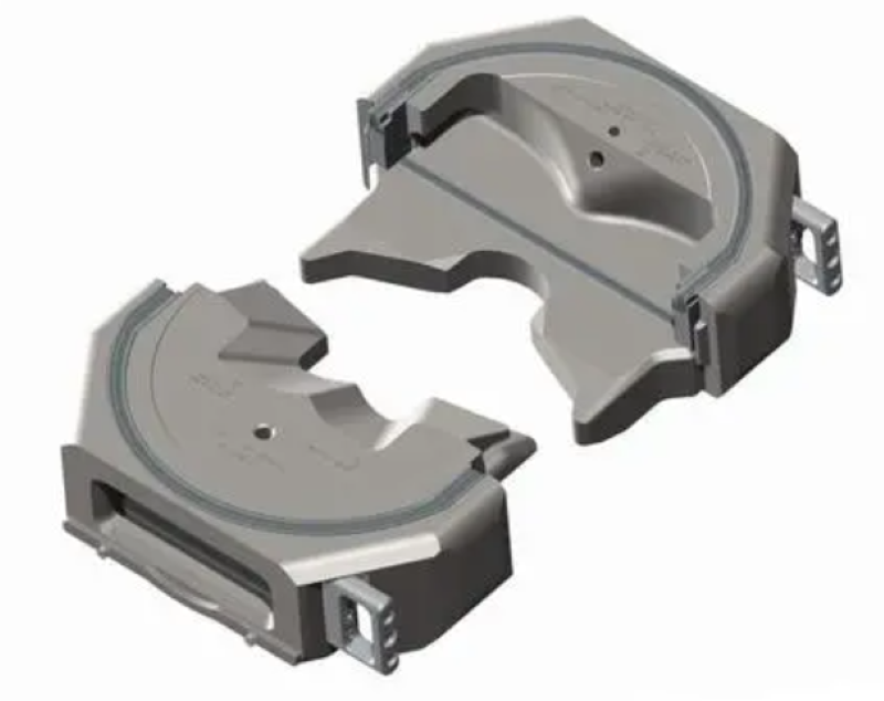
Pipeline rams – sealing on pipelines
A ram that seals the steel wire rope in the pipeline or hole. This block is specifically designed for specific sizes of drill pipes, tubing, casing, or wire ropes.
Variable ram of blowout preventer
The pipeline ram plate can also be a variable orifice block, which can be sealed within a certain size range.
Variable rams were introduced in 1979. In addition, these rams extend the versatility of ram type blowout preventers by sealing pipes of various sizes. This flexibility can eliminate the need to replace the ram when running a conical drill string or using tubing for testing. Variable rams use steel fingers that move inward to seal pipes smaller than the ram body.
Generally speaking, all ram blowout preventer manufacturers provide variable aperture rams that can be closed and sealed over a certain range of pipeline diameters. These rams are particularly useful when using conical columns or when adding another ram blowout preventer due to space limitations in the substructure. In addition, if aluminum drill pipes are used, it cannot always be ensured that conventional rams are used for effective sealing, as the diameter near the drill pipe joint is greater than the diameter in the middle of the joint.
The hanging potential of variable aperture rams is limited, depending on the size of the pipeline they seal. For example, Cameron variable bore rams (13-5/8 “U, suitable for 5” to 2-7/8 “) will support 450000 pounds of 5” drill pipe or 150000 pounds of 3-1/2 “drill pipe. Most variable aperture rams are constructed in a similar manner, with the key component being a feedable rubber packer.

Blind Rams
Generally, there are two types of rams that do not have pipe openings and can be closed on open hole. The most widely used is the blind rams.
Shear ram
Another type of blowout preventer ram that we can close in the naked eye is the shear ram. Shear rams are designed to cut oil pipes, drill pipes, or casing, and can also seal open holes (shear rams are mainly used for subsea stacking).
Feature
Secondary BOP Ram Shaft Seal
On many ram preventers, there is a “drain hole” on the lower side of the preventer body. This hole is aligned with the “stroke” of the plunger. The drain hole is actually aligned with the auxiliary connecting rod shaft seal to indicate leakage in these seals. If necessary, remove the cap screws and use an Allen wrench to inject plastic sealant around the plunger shaft between the check valve and the seal to temporarily prevent leakage.
BOP ram locking device
Many rams have manual locking devices. After the plunger is in the fully closed position, the lock will be activated. In this case, the hydraulic manufactured ram is locked by clockwise rotation of the tail rod. The locking device moves downwards along the guide screw and contacts the rear of the piston, mechanically locking it in the closed position. The locking device must be retracted in order to reopen the plunger.
If the hydraulic system malfunctions, a locking device can be used to close the plunger. If this is done, the plunger can only be reopened hydraulically.
Hydraril MPL plunger lock
The MPL locking mechanism is controlled by a one-way clutch and a locking nut. The clutch holds the nut and plunger in the locked position until the clutch is disengaged by applying hydraulic opening pressure. This will release the clutch plate, allowing the locking nut to rotate freely and open the plunger. Even if the closing pressure drops to 0 psi, the plunger will remain closed and locked.
Shaffer Pos – Lock Ram Lock
When closing pressure is applied, the piston moves inward with the locking cone and closes the plunger. When the piston reaches the fully closed position, the locking cone is forced inward by the closing hydraulic pressure and spring force, and the locking section slides towards the piston OD on the locking shoulder.
The locking cone fixes the locking section in place. Its function is like the second piston inside the main piston, pushing inward by closing pressure and outward by opening pressure. When opening pressure is applied, the locking cone moves outward, causing the locking section to slide along the conical locking shoulder towards the piston ID. Then, the piston moves freely to the fully open position.

 By Sun

