Classification and Application of Breather valve
Introduction
Breathing valve is to ensure that the tank space in a certain pressure range and atmospheric isolation, but also in excess of or below this pressure range with the atmosphere (breathing) of a valve. Its role is to prevent the tank due to overpressure or vacuum damage, while reducing the evaporation loss of liquid storage. Set breathing valve can not only reduce the tank gas emissions, thereby reducing the pollution of the atmosphere, but can make the tank to avoid damage due to overpressure or ultra-vacuum and lead to destabilization, safety and environmental protection have played a certain role in promoting.

Working principle
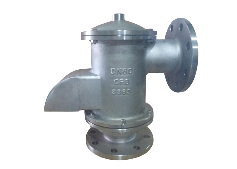
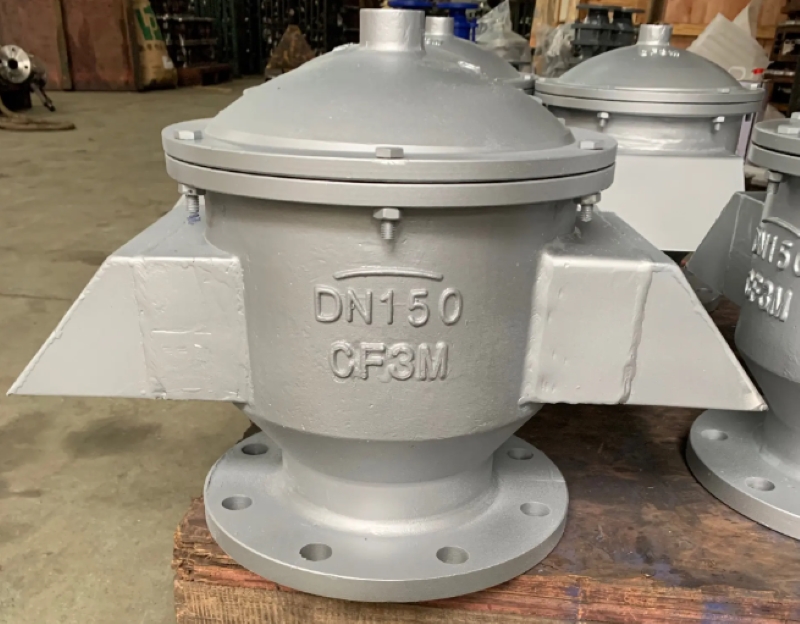
The breathing valve mainly consists of a valve seat, a valve cover, a protective cover, and two sets of opening and closing devices controlled by vacuum and pressure. The opening and closing device includes valve discs, guide rods, springs, spring seats, and sealing rings. When the pressure inside the tank reaches the rated positive exhalation pressure, the pressure valve disc opens and the vapor inside the tank is discharged; When the vacuum inside the tank reaches the rated suction negative pressure, the vacuum valve disc opens and air enters
The breathing valve fully utilizes the pressure bearing capacity of the storage tank itself to reduce medium emissions. Its principle is to use the weight of the positive and negative pressure valve discs to control the exhaust positive pressure and suction negative pressure of the storage tank; When the medium is extracted from the outside of the tank, the pressure in the upper gas space inside the tank decreases, reaching the operating negative pressure of the breathing valve. The atmosphere outside the tank will open the negative pressure valve disc of the breathing valve, allowing external gas to enter the tank, causing the pressure inside the tank to no longer continue to decrease, and balancing the air pressure inside and outside the tank to protect the safety device of the tank.
Working condition
The breathing valve functions as a seal under normal conditions to prevent gas leakage from the storage tank. The breathing valve only starts working under the following conditions.
(1) When the storage tank outputs materials outward, the breathing valve begins to inhale air into the tank.
(2) When filling the storage tank with materials, the breathing valve starts to exhale the gas inside the tank towards the outside.
(3) Due to climate change and other reasons, if the vapor pressure of the materials in the tank increases or decreases, the breathing valve will exhale steam or inhale air or nitrogen, which is commonly referred to as the thermal effect.
(4) When a fire occurs, the storage tank experiences a significant increase in liquid evaporation due to heating, and the breathing valve begins to exhale outward to avoid damage to the storage tank due to overpressure.
(5) In other working conditions, such as pressurized transportation of volatile liquids, chemical reactions in internal and external heat transfer devices, operational errors, etc., the breathing valve exhales or inhales to avoid damage to the storage tank due to overpressure or vacuum.

Classification
According to the working principle
The first method is to exhale or inhale when reaching a certain level of pressure; The other is designed to be purely exhaling without inhaling, which can be understood as using two one-way valves with appropriate pressure instead.
The second type of breathing valve is similar to a one-way check valve, which can only exhale outward and cannot inhale inward. When the pressure in the system increases, the gas will be vented outward through the breathing valve to ensure a constant pressure in the system. For storage tanks that store toxic substances, there is no breathing valve and treatment devices such as activated carbon filters can be added.
Breathing valves are generally used on atmospheric or low-pressure storage tanks, meaning that only atmospheric and low-pressure storage tanks have respiratory emissions (steam recovery systems are often installed on low-pressure tanks), while high-pressure storage tanks have no emissions, no respiratory or operational losses.
The main emissions of fixed top tanks are divided into respiratory loss (small respiratory emissions) and work loss (large respiratory emissions).
Selection
- The requirements for installation location and temperature range, such as the selection of all-weather breathing valves in cold areas, and the selection of pipeline type breathing valves for installation in pipelines.
- The control pressure of the mechanical breathing valve should be adapted to the relevant pressure bearing capacity.
- The specifications (flange diameter) of the mechanical breathing valve should meet the maximum inlet and outlet breathing gas flow requirements of the oil tank.
For the selection of oil storage tanks: According to the Chinese petroleum and natural gas industry standard SY/T0511-1996 “Breathing Valves for Oil Storage Tanks”, the selection principles for the specifications and dimensions of breathing valves are as follows:
Select the size and quantity of breathing valves based on their ventilation capacity per unit time. Calculate the flow rate range of exhaled or inhaled gas based on the ventilation volume of different specifications, sizes, and pressure levels. Determine the number and specifications of the selected breathing valves based on the flow rate of oil received and received per unit time of the oil tank.
Compare the performance curves of various specifications of breathing valves provided by the breathing valve manufacturer for exhalation or inhalation at various pressure levels, and select the size of the breathing valve.
The takeoff pressure of the breathing valve should be lower than the design pressure of the storage tank where the breathing valve is located to protect the storage tank from damage, but should be higher than the operating pressure of the storage tank to ensure normal operation of the storage tank.
Maintenance
First, gently open the valve cover, take out the vacuum valve disc and pressure valve disc, and check the sealing area between the valve disc and the valve disc, as well as the valve disc guide rod and guide rod sleeve for oil and dirt. If any oil or dirt is found, it should be cleaned up and then installed back in place. Pull up and down a few times to check whether the opening is flexible and reliable. If everything is normal, then cover and tighten the valve cover.
During maintenance and upkeep, if any abnormal phenomena such as scratches or wear are found on the valve disc, it should be replaced immediately or contact the supplier company to ensure timely resolution.

 By Sun

